Advanced Forming Research CentreMaterial behaviour

We are shining a light on materials science and residual stress within manufacturing– with huge benefits for industry.

Understanding the effects of manufacturing processes on products means that we can increasingly employ a predictive approach, which boosts efficiency and saves time and money during costly trials. Materials characterisation expertise also helps our customers make better manufacturing decisions and overcome production problems.

Our state of the art laboratory for residual stress evaluation and strain mapping, the only one of its kind in Scotland, is where the materials magic happens.  One of the very few labs across the UK that is ISO 17025 accredited for relevant measurement techniques, we provide far more than purely testing, offering a range of solutions, industrial expertise and materials intelligence.
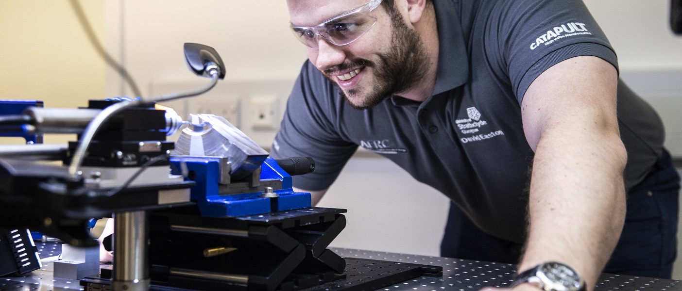
Advanced materials characterisation

Describing how materials behave under certain conditions enhances our understanding and modelling capability, allowing us to be genuinely predictive. We benefit from a full suite of characterisation equipment, chosen for its ability to replicate strain rates, deformation rates and temperatures across full-scale industrial forging and forming equipment. The jewel in the crown is our bespoke Phoenix testing machine, which is a unique high performance forge simulator. We employ a holistic approach to materials characterisation, encompassing modelling and prediction, processing, testing and validation, all under one roof.

Technical info:

Examines the mechanical behaviour of materials under compression, tensile and cyclic loading conditions.  Ideal for measuring the material properties of flow formed parts.  Provides enhanced control but less maximum strain than hydraulic driven machines.  Allows high temperature testing of materials and uses bespoke software for complex testing modes involving rapid changes to the strain rate.

  • Load capacity: 250 kN 
  • Max. temperature: 1,250°C
  • Max. height of test frame: 3,040 mm
  • Strain rates: 0.1s-1 to 3s-1
  • Displacement rates of up to 150 mm per second

Technical info:

Used to study the mechanical behaviour of materials under compression, tensile and cyclic loading conditions. A hydraulic drive, as opposed to screw, allows for higher strain rates and larger loads.   Primarily used testing at higher strain rates than those covered by the Z250 and typically supports material characterisation programmes linked to the simulation of forging process.

  • Load capacity: 250 kN
  • Max. temperature: 1,250°C
  • Max. height of test frame: 3,040 mm
  • Strain rates: 0.1s-1 to 3s-1 
  • Displacement rates of up to 150 mm per second


Technical info:

Like the above but with less maximum strain, this features an MTS extensometer and GOM® Aramis for deriving the plastic strain ratio (r) value.  Can be used for strain rate jump testing, stress relaxation testing and controlled in either a positional, load-controlled or true strain rate mode.

  • Load capacity: 150 kN
  • Temperature capacity: 1,400°C
  • Low strain rates: 10-5s-1 to 0.5s-1

Technical info:

Developed by the AFRC National Physical Laboratory (NPL) for testing metals and other conductive materials. Ideal for micro type samples we don’t want to destroy through mechanical testing. Also useful for creating a full tensile test from a small sample. Can achieve high fatigue loading rates and very rapid rates of heating and cooling.

  • Load capacity: 5 kN
  • Resistance heating: 400 amps
  • Environmental chamber (vacuum, protective atmosphere)

Technical info:

For conducting experiments in the range of, 'medium’, strain rates in compression, up to a maximum of 200s-1, at high temperatures up to 1150C. Ideal for detailed simulation of thermo-mechanical conditions taking place during hot forging in screw presses and hammers. Supports study and prediction of the mechanical behaviour of alloys under forging conditions by providing data for use in modelling and simulation.

  • Maximum testing load: 600 kN 
  • Max. speed: 3.6 m/s
  • Speed control: +/- 5% 
  • Temperature capability: 1,150°C (material dependent)

Technical Info:

Used for structural and chemical analysis of metallographic specimens, this offers high flexibility to increase performance and versatility. It can achieve magnification of up to 1,000,000x, providing high resolution image in a digital format. Also operates at low vacuum, enabling the imaging of non-conductive samples. Designed to provide maximum data- imaging and microanalysis from all specimens, with or without preparation.

  • Magnification: 14 x to 1,000,000 x
  • Max. electron beam resolution: 3 nm at 1kV

Technical info:

Similar to the above, used for structural and chemical analysis of metallographic specimens.

  • Magnification: 6 x to 1,000,000 x
  • Max. electron beam resolution: 3 nm at 1kV

Technical info:

Used inside a scanning electron microscope (SEM) allowing in situ studies for examining materials at grain level. Can be used as an integrated system within the SEM, fitted inside the electron microscope chamber (max. temperature 1200C), or as a 'bench top,' micro thermo-mechanical tester in the laboratory (max. temperature 200°C). Operates in tension, cyclic tension-compression, and 4-point bend test modes.

  • Load capacity: 5 kN
  • Max. temperature: 1,200°C

Technical info:

A non-contact and material-independent measuring system based on digital image correlation. Performs high-precision measurements independently from geometry and temperature without time-consuming and expensive preparation. Provides 3D surface coordinates, 3D displacements and velocities, surface strain values and strain rates. Used for determination of materials properties, component analysis, and verification of FEA and real-time control of testing devices.

  • Camera resolution: 2,448 x 2,050 px 
  • Frame rate: 15 Hz up to 29 Hz
  • Camera resol. 2,448 x 2,050 px

Technical info:

Widely used here at the AFRC but rare out in the field, this hydraulically operated testing machine is used to study the room temperature formability of sheet materials. Conducts techniques and tests such as Nakajima test, Marciniak test, Ericsson test, earing test and cupping test. The machine’s low piston-cylinder friction enables accurate measurement recording and excellent reproducibility.

  • Max. test load: 1,000 kN 
  • Max. ram stroke: 150 mm
  • Max. deep drawing speed: 750 mm/min
  • Max. sample size: 260 mm wide

Technical info:

A key piece of equipment used by our materials team. Often used alongside our Instron Electro-Thermal Mechanical Tester and Zwick machines to create strain maps, which provide a comprehensive picture of material properties. A powerful piece of equipment that is particularly useful for complex and small parts, allowing for the attachment of a gauge when necessary.

  • Displacement resolution: 0.01 pixel
  • 2D and 3D displacement mapping
  • Captures images at high strain rate tests such as compression tests at 5m/s speed or up to 200 1/s true strain rates


Technical info

Used for optical analysis of metallographic specimens and is equipped for brightfield, darkfield, DIC and simple polarisation observations.

Technical info:

Used for optical analysis of metallographic specimens, this offers macro magnification that gives four times the field of view of conventional scanning objectives.

Residual stress measurement, modelling and management

Residual stress is a common, but often unidentified, side effect of many manufacturing processes. This locked in energy can lead to unexpected consequences, such as the early failure of a part or distortion out of required tolerances. It can also be favourable and used to stop materials from cracking or extend the life of a product. As one of the top teams in the world for evaluating, understanding and managing residual stress within manufacturing, we benefit from access to industrial equipment and modelling expertise. This brings numerous benefits to our customers including materials savings, enhanced efficiency and a deeper understanding of their products and processes. Key kit:

The AFRC’s residual stress measurement and strain mapping lab enables us to measure surface, sub-surface and bulk residual stresses using the following techniques:

  • X-Ray Diffraction (XRD)
  • Incremental Central Hole Drilling (ICHD)

1.      ICHD based on Strain Gauge Rosette

2.      ICHD based on Electronic Speckle Pattern Interferometry (ESPI)

  • Contour Method
  • Slitting Method
  • Digital Image Correlation (DIC) for displacement and strain mapping

Technical info:

A high-powered residual stress mapping machine used to measure large components and work hardened metals.  Over two meters of measurement space, heavy-duty XY mapping stages, and a removable mapping stage.  Provides flexibility to meet all complex measurement needs and measures surface residual stress in a range of materials including Ti alloys, Ni alloys, Al alloys, steel and stainless steel.

Technical info:

A conventional hole drilling system used for automatic step-by-step drilling and strain measurement with a controllable feed rate. Fully automatic process and automatic drilling, its user can select a number of drilling steps, profiles and feed rates. Offers high repeatability and high speed drilling, providing high measuring accuracy.

  • Max. turbine speed: 400,000 RPM
  • Max. turbine feed pressure: 5 bar
  • Drilling resolution: 5 µm
  • Drilling speed range: 0.03 – 1 mm/mi

Technical info:

Measures residual stresses by drilling a narrow hole into a component and using a laser light source and video recording equipment to measure distortions. This type of testing is semi -destructive and benefits from requiring little surface preparation before measuring.  It provides measurements of near-surface residual stresses from distances as close as 10µm from the surface.

  • Max. turbine speed: 50,000 RPM 
  • Max. turbine feed pressure: 5 bar 
  • Drilling resolution: 5 µm
  • Drilling speed range: 0.001 – 0.4 mm/sec

Technical info:

Ideal test for analysing full field measurements. Used to determine residual stresses at any depth while handling changes in microstructure without reducing reliability of results. A fully destructive test, it can also be difficult to apply to complex geometries. Determines residual stress through cutting and measuring surface height maps, or contours, on the free surfaces created by the cut.

Technical info:

Involves cutting a slit across a component, typically using wire-EDM, and measuring the surface strains with strain gauges located underneath or next to the slit. A destructive mechanical strain release (MSR) technique that can accurately measure both near surface and through thickness residual stresses.


Technical info:

Allows us to determine surface displacement due to the material deformation via consecutive optical observations. It numerically analyses a digitised intensity image of an object in the deformed state and cross correlates it with the same object in the original image to determine the displacements between the two images. 

  • Measures in 2D and 3D
  • Measures from micro-macro scales
 

Technical info:

A non-destructive residual stress measurement technique. It offers the capability of measuring surface, subsurface and bulk residual stresses. This is achieved by using differently angled transducers to send and receive the ultrasound. This system is in continuous development.

  • Stress can be measured in materials with thickness 2 - 150 mm 
  • Error of stress determination (from external load): 5 - 10 MP
 

Materials preparation

  • Buehler VibroMet 2 Vibratory Polisher
  • Buehler EcoMet 300 Grinder Polisher
  • Struers LectroPol-5 Electrolytic Polishing Machine
  • Buehler Abrasimatic 300 Abrasive Cutter